2. CENELEC EN 50128
2.1. Overview
EN 50128 governs software used in railway control and protection applications, i.e., systems that ensure the safe and efficient movement of trains. Examples include:
Automatic Train Protection (ATP), which ensures automatic braking to avoid collisions or overspeed;
Interlocking Systems, which prevent conflicting train movements through tracks, signals, and switches;
Train Control Management Systems (TCMS), which coordinate control of subsystems (doors, brakes, traction);
Level Crossing Protection, which manages gates and warnings at road-rail intersections; and
Centralized Traffic Control (CTC), which oversees train routing and dispatch across large regions.
The goal of the standard is to provide confidence that the software functions reliably and safely relative to its SIL. To this end it specifies requirements in areas including the following:
Software development lifecycle processes;
Verification and validation;
Tools, techniques, and documentation;
Risk mitigation measures; and
Assessment of compliance with the standard.
More specifically, EN 50128 identifies the procedures and prerequisites (organization, independence and competencies management, quality management, V&V team, etc.) applicable to the development of programmable electronic systems used in railway control and protection applications. The standard therefore may apply to some software applications in the rail sector but not necessarily to all.
EN 50128 is used in both safety-related and non-safety-related applications and applies exclusively to software and its interaction with the whole system. (In light of its role in the certification of non-safety-related software, the standard introduces the Safety Integrity Level "Basic Integrity", which pertains to software that is not safety related.)
Although EN 50128 is targeted to the rail industry, it is not intrinsically domain specific. The standard is basically a specification of sound software engineering practices for long-lived large-scale high-assurance systems in general and could in principle be applied in other domains.
One of the distinctive points of EN 50128 is its requirement to justify the implementation of the resources. For this reason, it is said to be a "resources standard".
2.2. Structure of the standard
Fig. 6 illustrates the structure of EN 50128 (note that chapters in CENELEC standards are referred to as clauses, and individual sections and sub-sections within a chapter are sub-clauses).
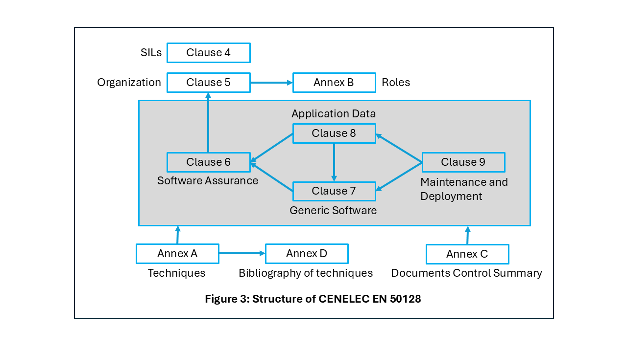
Fig. 6 Structure of CENELEC EN 50128
Clauses 1, 2, and 3 — Scope, Normative references, and Terms, definitions and abbreviations, respectively — provide context and basic information.
Clause 4, Objectives, conformance and software safety integrity levels, identifies the five Safety Integrity Levels and states the criterion for conformance to the standard:
To conform to this European standard it shall be shown that each of the requirements has been satisfied to the software safety integrity level defined and therefore the objective of the sub-clause in question has been met.
This clause also specifies the role of normative Annex A in the selection of techniques and measures for satisfying the requirements, and the means for verifying compliance (inspection of the required documents, augmented when appropriate by other evidence such as auditing and the witnessing of tests).
Clauses 5 through 9 form the core of the standard, with sub-clauses providing the following content:
Objective: the purpose of meeting the requirements specified in the sub-clause
Input documents (if applicable)
Output documents (if applicable)
Requirements: Details on what the software supplier needs to do or provide. In some cases the requirements reference the tables in Annex A for specific techniques or measures to be used.
Clause 5, Software management and organization, covers three topics:
Organization, roles and responsibilities (sub-clause 5.1);
Personnel competence (sub-clause 5.2); and
Lifecycle-related issues (sub-clause 5.3).
The standard does not dictate a specific lifecycle, but it cites the "V" approach as a recommendation, from the software specification to the overall software testing and integration, and also imposes some requirements. For example, the chosen lifecycle model needs to account for potential iterations between phases, and detailed documentation in the Software Quality Assurance Plan as specified in sub-clause 6.5 has to be supplied.
Clause 6, Software assurance, has the goal of achieving a software package with a minimum level of error and involves a variety of activities and technologies:
Software testing (sub-clause 6.1);
Software verification (sub-clause 6.2) — defined in sub-clause 3.1.48 as "confirmation, through the provision of objective evidence, that specified requirements have been fulfilled";
Software validation (sub-clause 6.3) — defined in sub-clause 3.1.46 as "confirmation, through the provision of objective evidence, that the requirements for a specific intended use or application have been fulfilled";
Software assessment (sub-clause 6.4);
Software quality assurance (sub-clause 6.5);
Modification and change control (sub-clause 6.6); and
Support tools and languages (sub-clause 6.7) — see Tool qualification below.
As shown in [1], for software applications the assessment process involves demonstrating that the software application achieves its associated safety objectives.
EN 50128 makes a clear separation between the application software, referred to as the generic software (Clause 7), and the data or algorithms that are used to configure the generic software (Clause 8).
Clause 7, Generic software development, has the following sub-clauses:
Lifecycle and documentation for generic software (sub-clause 7.1);
Software requirements (sub-clause 7.2);
Architecture and Design (sub-clause 7.3);
Component design (sub-clause 7.4);
Component implementation and testing (sub-clause 7.5);
Integration (sub-clause 7.6); and
Overall Software Testing / Final Validation (sub-clause 7.7).
Clause 8, Development of application data or algorithms: systems configured by application data or algorithms, ensures that the configuration parameters are verified and validated with the same degree of assurance, based on the relevant SIL, as is needed for the generic software that they configure.
An important part of the standard is Clause 9, Software deployment and maintenance. As stated in sub-clauses 9.1.1 and 9.2.1, the objectives of this clause are, respectively:
To ensure that the software performs as required, preserving the required software integrity level when it is deployed in the final environment of the application.
and
To ensure that the software performs as required, preserving the required software integrity level and dependability when making corrections, enhancements or adaptations to the software itself.
Annex A (normative), Criteria for the Selection of Techniques and Measures, contains a set of tables that correlate the artifacts and practices (documentation, techniques, and measures) specified elsewhere in the standard, with an indication of whether, and how strongly, they are recommended based on the software's SIL:
M: Mandatory. Must be used
HR: Highly Recommended. If not used, need to explain rationale for using alternative technique
R: Recommended
--: No recommendation either for or against usage
NR: Not recommended. If used, need to explain rationale for decision
Annex A consists of two sub-clauses:
Clauses tables (A.1); the table headings identify the sub-clause(s) containing the relevant requirements:
Table A.1 – Lifecycle Issues and Documentation (5.3)
Table A.2 – Software Requirements Specification (7.2)
Table A.3 – Software Architecture (7.3)
Table A.4 – Software Design and Implementation (7.4)
Table A.5 – Verification and Testing (6.2 and 7.3)
Table A.6 – Integration (7.6)
Table A.7 – Overall Software Testing (6.2 and 7.7)
Table A.8 – Software Analysis Techniques (6.3)
Table A.9 – Software Quality Assurance (6.5)
Table A.10 – Software Maintenance (9.2)
Table A.11 – Data Preparation Techniques (8.4)
Detailed tables (A.2); these are lower-level tables that expand on certain entries in the Clauses tables:
Table A.12 – Coding Standards
Table A.13 – Dynamic Analysis and Testing
Table A.14 – Functional/Black Box Test
Table A.15 – Textual Programming Languages
Table A.16 – Diagrammatic Languages for Application Algorithms
Table A.17 – Modeling
Table A.18 – Performance Testing
Table A.19 – Static Analysis
Table A.20 – Components
Table A.21 – Test Coverage for Code
Table A.22 – Object Oriented Software Architecture
Table A.23 – Object Oriented Detailed Design
As an example, Table A.4 contains a row for the programming language(s) selection:
Technique/Measure |
Ref |
Basic Integrity |
SIL 1 |
SIL 2 |
SIL 3 |
SIL 4 |
... |
... |
... |
... |
... |
... |
... |
10 Programming Language |
Table A.15 |
R |
HR |
HR |
HR |
HR |
... |
... |
... |
... |
... |
... |
... |
Table A.15 contains a row for Ada:
Technique/Measure |
Ref |
Basic Integrity |
SIL 1 |
SIL 2 |
SIL 3 |
SIL 4 |
ADA |
D.54 |
R |
HR |
HR |
HR |
HR |
... |
... |
... |
... |
... |
... |
... |
Sub-clause D.54 (Suitable Programming languages) notes the features that a suitable language should have (e.g., run-time array bound checking), and features that it should encourage (e.g., definition of variable sub-ranges). On the other side, D.54 also lists features that should be avoided because they complicate verification (e.g., implicit variable initialization).
The entries in Tables A.4 and A.15 show that Ada is a Highly Recommended language at SIL 1 through SIL 4 and a Recommended language at the Basic Integrity level. Features that should be avoided can be detected and prevented by using AdaCore's GNATcheck tool in the GNAT Static Analysis Suite; see GNAT Static Analysis Suite (GNAT SAS).
Annex B (normative), Key software roles and responsibilities, consists of ten tables detailing the responsibilities and key competencies for the various roles specified in the standard: Requirements Manager, Designer, Implementor, Tester, Verifier, Integrator, Validator, Assessor, Project Manager, and Configuration Manager.
Annex C (informative), Documents Control Summary, provides a table that lists, for each project phase, its output documents and, for each document, the responsible author and reviewer(s). The lifecycle phases and their associated document count are:
Planning: 5 documents
Software requirements: 3 documents
Architecture and design: 6 documents
Component design: 3 documents
Component implementation and testing: 3 documents
Integration: 3 documents
Overall software testing / Final validation: 4 documents
Systems configured by application data/algorithms: 8 documents
Software deployment: 5 documents
Software maintenance: 4 documents
Software assessment: 2 documents
Annex D (informative), Bibliography of techniques, details the aim and description for seventy-one specific software engineering practices. These are applicable at various lifecycle phases; for example:
Coding Standards and Style Guide (sub-clause D.15) and Language Subset (sub-clause D.35) at the design and implementation phase,
Formal Methods and Formal Proof (sub-clauses D.28 and D.29) at the implementation and verification phases, and
Equivalence Classes and Input Partition Testing (sub-clause D.18) at the testing phase.
Annex ZZ (Informative), Relationship between this European standard and the essential requirements of EU Directive 2016/797/EU [2016 OJ L138] aimed to be covered was introduced in EN 50128/A1. It contains a table showing the relationship noted in the Annex title.
2.3. Tool qualification
An earlier edition of the standard, EN 50128:2001, introduced a requirement that the compilers employed for a project be purpose-certified, but did not give a clear indication of what precisely was expected. Clause 6.7 in the 2011 revision formalizes this concept, which will be referred to here as "tool qualification", and provides details on what needs to be performed and/or supplied. (The standard does not use a specific term for this process, but the "tool qualification" terminology from the airborne software standards DO ‑ 178C/ED ‑ 12C [2] and DO ‑ 330/ED ‑ 215 [3] is appropriate.)
2.3.1. Tool classes
Tool qualification is based on the recognition that different tools need different levels of confidence in their reliability, based on how a tool error affects the application software. This is formalized in the concept of a "tool class". As stated in sub-clause 6.7.1:
The objective is to provide evidence that potential failures of tools do not adversely affect the integrated toolset output in a safety related manner that is undetected by technical and/or organisational measures outside the tool. To this end, software tools are categorised into three classes namely, T1, T2 & T3 respectively.
T1 is reserved for tools that affect neither the verification of the software nor the final executable file.
T2 applies to tools where a fault could lead to an error in the results of the verification or validation. Examples include tools used for verifying compliance with a coding standard, generating quantified metrics, performing static analysis of the source code, managing and executing tests, etc.
T3 applies to tools where a fault could have an impact on (and, for example, introduce errors into) the final executable software. This class includes compilers, code generators, etc.
Sub-clause 6.7 of EN 50128 defines a set of recommendations for each tool class; these affect the content of the tool qualification report. The standard identifies twelve requirements (numbered from 6.7.4.1 to 6.7.4.12) concerning tool qualification. Requirement 6.7.4.12 is a mapping from each tool class to the applicable sub-clauses in the standard. It is shown here in the table below, which augments the version in the standard by also specifying the lifecycle phase that is relevant for each sub-clause. The steps shown indicate the requirements to be met and reflect the additional effort needed as the tool level increases; for further information, please see [4], Chapter 9.
Tool class |
Applicable sub-clause(s) |
Lifecycle phase |
|---|---|---|
T1 |
6.7.4.1 |
Tool identification |
T2 |
6.7.4.1 |
Tool identification |
6.7.4.2 |
Tool justification |
|
6.7.4.3 |
Tool specification/manual |
|
6.7.4.10, 6.7.4.11 |
Tool version management |
|
T3 |
6.7.4.1 |
Tool identification |
6.7.4.2 |
Tool justification |
|
6.7.4.3 |
Tool specification/manual |
|
(6.7.4.4 and 6.7.4.5) or 6.7.4.6 |
Tool conformity evidence |
|
(6.7.4.7 or 6.7.4.8) and 6.7.4.9 |
Tool requirement fulfillment |
|
6.7.4.10, 6.7.4.11 |
Tool version management |
2.3.2. AdaCore tool qualification support
As will be explained below, AdaCore supports EN 50128 compliance through tools qualified for several purposes:
Static and dynamic analysis;
Code verification including formal proof; and
Compilation with traceability and reproducibility guarantees.
These capabilities reduce certification risk while improving code quality and lifecycle confidence.
AdaCore's qualification packages contain the information required by EN 50128, such as documentation, history, infrastructure, user references, recommended usage, validation strategy, configuration management and change tracking.
Furthermore, tools can be provided through a subscription service known as "sustained branches" (see Sustained Branches). In this mode, a specific version of the tools can be put into special maintenance, where AdaCore can investigate known problems and provide repairs or work-arounds for potential issues on these branches without unrelated updates that may risk regressions.
AdaCore's decades-long experience in software certification for embedded and safety-critical domains, including rail and avionics, ensures that customers have access to:
Qualification material for EN 50128 and/or DO ‑ 330/ED ‑ 215 tool assessment;
A formally verifiable language (SPARK) for high-integrity use cases; and
Lifecycle support aligned with the needs of long-term platform deployments
Bibliography